
Initial Steps
Take note of the following:
1. The IP address and subnet of your computer.
2. The IP address of the ATEM switch.
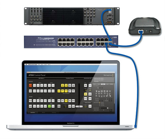
Connect the Transmitter to the same network as your computer and ATEM switch. You may need to use a standard Ethernet switch or hub if you currently have a direct connection between your ATEM and computer.
The default Transmitter settings are as follows. You may need to reset the Transmitter to obtain these settings. Please review the reset procedures below.
Default IP: 192.168.1.234
Points to ATEM at: 192.168.1.240
To change the previous settings use your browser and the 192.168.1.0 network with a mask of 255.255.255.0 and connect to the Transmitter by opening your browser at:
http://192.168.1.234/
For your system to work you must have the Transmitter, ATEM and your computer be on the same network. An example of that would be:
Computer IP: 192.168.1.2
Transmitter IP: 192.168.1.234
ATEM IP: 192.168.1.240
Consult your network professional for assistance if none of this information is making sense.
Transmitter Reset Procedures
1. Power on the Transmitter
2. Push the reset button by using a paper clip through the pinhole found on the top of the device.
3. Restart the Transmitter by powering it off and then back on
Transmitter
| Default | Settings |
|---|---|
| IP: | 192.168.1.234 |
| MAC: | DE:AD:BE:EF:FE:ED |
| Switcher IP | 192.168.1.240 |
| Switcher PORT | 49910 |
LED States
| RED: | Not connected to ATEM |
| BLUE: | Connected to ATEM |
| RED BLINK | Packet Sent |
Receiver
A receiver receives radio signals from the transmitter and triggers either the PROGRAM LED or the PREVIEW LED according to the transmitter and ATEM.
LED States
| POWER-ON BLUE BLINK: | Blinks node # or rapidly for test mode |
| CONSTANT BLUE BLINK: | In test mode (receiving radio signal) |
| RED: | Node # is on PROGRAM |
| GREEN: | Node # is on PREVIEW |
Test Mode
Setting the Receiver's node # to 0 (all DIP pins off) will turn on the test mode. When in test mode the Receiver will blink BLUE every 1 second if it's receiving a radio signal from the Transmitter. While powering on the Receiver in test mode the LED will blink BLUE rapidly for one second to indicate the current mode.
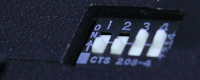
Node DIP Switch
The node DIP pins are binary-based. For example, when the DIP pins are 0110, the node # is 5.
Note: The receiver needs to be restarted whenever the node # is changed.
 |
||||
| NODE | DIP1 | DIP2 | DIP3 | DIP4 |
|---|---|---|---|---|
| 0 | OFF | OFF | OFF | OFF |
| 1 | OFF | OFF | OFF | ON |
| 2 | OFF | OFF | ON | OFF |
| 3 | OFF | OFF | ON | ON |
| 4 | OFF | ON | OFF | OFF |
| 5 | OFF | ON | OFF | ON |
| 6 | OFF | ON | ON | OFF |
| 7 | OFF | ON | ON | ON |
| 8 | ON | OFF | OFF | OFF |
| 9 | ON | OFF | OFF | ON |
| 10 | ON | OFF | ON | OFF |
| 11 | ON | OFF | ON | ON |
| 12 | ON | ON | OFF | OFF |
| 13 | ON | ON | OFF | ON |
| 14 | ON | ON | ON | OFF |
| 15 | ON | ON | ON | ON |
Troubleshooting
Inconsistent Behavior of Lights
Make sure that the Receiver is fully charged before further testing. A single charge should be sufficient for more than 24 hours of continuous usage. A full charge requires about an hour of charging from a 5v USB source.
Limited Range
The devices are designed for a line-of-sight use of about 150ft. Further range can be achieved by extending the internal wire antennas through the pre-drilled holes on both the Transmitter and Receiver(s). This procedure requires the disassembly of the enclosure using a Phillips screwdriver. Please note that the exposed antenna may break off if pulled on. Precautions need to be taken if this device will be used in a mobile environment. For example, consider placing a bead of epoxy on the wire antenna so that it will not be pulled further than needed as the bead will prevent unnecessary tension on the solder joint.
DIY Notes
Summary of Steps
Note: We're assuming that you have a transmitter board with the Arduino Ethernet and also a receiver board with a JeeNode.
- Copy the dependent libraries from the project's libraries directory to your systems Arduino libraries directory. You may need to overwrite some of the libraries.
- Upload ATEM_Tally_Receiver.ino to your receiver node.
- Upload ATEM_Tally_Transmitter.ino to your transmitter.
- Connect the transmitter to the same network as the ATEM switcher and power it on (it may take a minute to connect to ATEM).
- Set the node # on your receiver using the DIP pins using the binary notation. On power-on the receiver will blink the node # count. Once connected, the receiver will light up RED if on PROGRAM and GREEN if on PREVIEW.
Library Modifications
The RF12 library was slightly modified to allow the Arduino Ethernet to support both the Ethernet and the RF12 radio. Since Ethernet and the radio both use the same SS_BIT, they will conflict with each other. Leave Ethernet as it is and modify the RF12 library only. Note: There is a new class called RF12Mod which is a copy of RF12 with slight modifications.
Upgrade Transmitter to work with ATEM Switchers Firmware 6.0.x
- 1. You will need to purchase the FTDI interface for USB. Here is an example from SparkFun: https://www.sparkfun.com/products/9716
- 2. Install the Arduino IDE: http://arduino.cc/en/main/software
- 3. Download and Copy/Paste all the libraries in the TallyLight_4.2_Update.zip file to the libraries folder of your Arduino IDE installation. Note that the 4.2 Update file is compatible with the latest 6.0 Firmware.
- 4. Open the ATEM_Tally_Transmitter_433MHz.ino sketch found in the same .zip file.
- 5. Set your IDE to USB device as UNO. (Make sure you have the correct USB port selected otherwise its just going to fail)
- 6. Open the Tally Light Transmitter and connect the FTDI interface to the FTDI pins (you may need to find a simple 6-pin right-angle header somewhere or just improvise)
- 7. Upload the sketch. If all is a success it should say "Complete".